


Selecting a substation steel structure is not simply a matter of choosing between a lattice frame and a tubular support. The structure has to carry defined electrical equipment and conductor loads while maintaining the geometry, clearances, connection points, and installation tolerances established by the project design.
For EPC contractors and utilities, the practical question is therefore: which type of steel structure is required at each location in the substation, and what information must be defined before fabrication?
Quick Answer
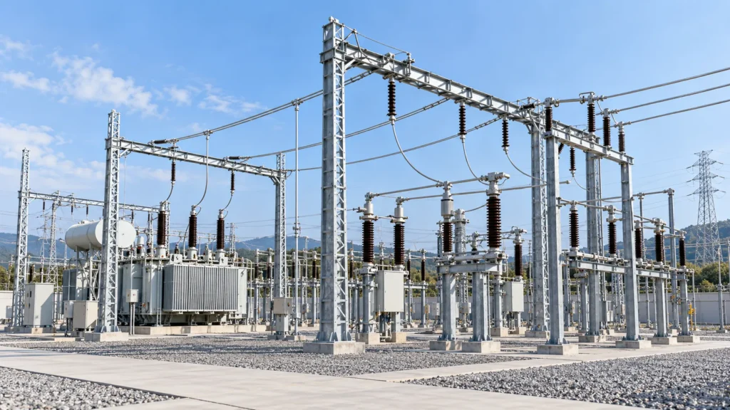
The main types of substation steel structures include gantries and portal frames, busbar support structures, equipment support structures, H-frames, equipment pedestals, cable support structures, and special steel frames. In an air-insulated substation (AIS), these structures may support conductors, insulators, rigid or flexible bus systems, circuit breakers, disconnect switches, instrument transformers, and incoming or outgoing line connections. GIS projects can require different support arrangements because much of the primary equipment is enclosed. The correct structure depends on the electrical layout, equipment loads, conductor forces, wind and seismic conditions, required clearances, foundation interface, corrosion environment, and applicable project standards.
1. Substation Gantry Structures
Substation gantries are among the most recognizable steel structures in an outdoor switchyard.
A typical gantry consists of vertical columns connected by one or more horizontal beams. Depending on the project, the columns may be lattice members, tubular sections, rolled sections, or fabricated members.
Gantries are commonly associated with:
- Incoming and outgoing transmission circuits
- Strain conductors
- Bus connections
- Insulator strings
- Line termination points
- Overhead electrical connections
Unlike a simple equipment pedestal, a gantry can be subjected to significant horizontal conductor forces in addition to gravity, wind, and other project-defined loads.
The electrical designer must establish conductor configuration, attachment locations, phase spacing, clearances, and expected loads before the structural system is finalized.
For procurement, do not specify a gantry by span and height alone. Conductor attachment loads, loading directions, allowable deflection, connection geometry, foundation interface, and applicable load combinations also matter.
2. Bus Support Structures
Bus support structures carry the bus conductors and associated insulators.
Their configuration varies substantially because substation bus systems themselves vary.
IEEE 605-2023 distinguishes two basic bus types used in air-insulated substations: rigid bus and strain (cable) bus. The bus selection influences the forces acting on the supporting structure and the number and arrangement of supports required.
A rigid bus arrangement may use individual posts, frames, or multi-column supports positioned at calculated intervals. A flexible or strain bus system transfers conductor tension into supporting structures.
Bus support design may therefore need to consider:
- Conductor dead load
- Insulator and hardware loads
- Wind
- Short-circuit forces
- Thermal movement
- Connection loads
- Project-specific seismic effects
- Required electrical clearances
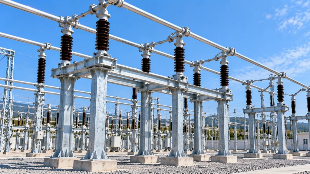
For buyers, one frequent mistake is treating a bus support as a generic fabricated steel frame. Its geometry is closely connected to the electrical bus design.
Changes in bus elevation, conductor size, support spacing, or equipment connection position can affect the structural requirements.
3. Equipment Support Structures
Equipment support structures place electrical equipment at the elevations and positions defined by the substation layout.
They may support equipment such as:
- Circuit breakers
- Disconnect switches
- Current transformers
- Voltage or potential transformers
- Surge arresters
- Insulators
- Other switchyard equipment
Configurations range from simple single-column pedestals to multi-column braced frames.
The equipment manufacturer should provide the loads and interface information needed for structural design. Depending on the equipment and project, relevant information can include equipment weight, center of gravity, bolt pattern, operating forces, terminal loads, seismic requirements, and installation tolerances.
This interface deserves particular attention during procurement.
A steel frame can meet its fabrication drawing and still create installation problems if its base plate, anchor bolts, equipment holes, or mounting elevations do not match the approved equipment interface.
4. H-Frames and Portal Frames
H-frames use two primary columns connected by a horizontal member. Portal frames follow a similar structural concept and may be used where a clear opening or wider support arrangement is required.
These configurations can provide a relatively simple load path and are adaptable to many substation layouts.
Depending on the electrical design, they may be used for:
- Bus supports
- Insulator supports
- Equipment support
- Conductor arrangements
- Auxiliary structural functions
The terms used by utilities and EPC contractors are not always identical. A structure described as an H-frame on one project may be classified under a broader equipment-support or bus-support schedule on another.
For that reason, procurement documents should rely on structure marks, approved drawings, loading schedules, and BOM references rather than names alone.
5. Equipment Pedestals and Individual Supports
Not every item requires a large frame.
Individual steel pedestals or posts can support smaller pieces of substation equipment or insulators. These structures usually have a base plate or embedded foundation interface at the bottom and an equipment-specific connection at the top.
Their apparent simplicity can make dimensional control especially important.
Check:
- Overall height
- Base plate dimensions
- Anchor bolt pattern
- Hole size and position
- Top plate orientation
- Equipment mounting holes
- Weld details
- Galvanized surfaces
- Structure identification
When many similar pedestals are used across a switchyard, clear piece marking and erection drawings can reduce the risk of installing the wrong support at the wrong bay.
6. Cable Support Structures and Cable Trays
Substations also contain structural systems for routing power, control, communication, and auxiliary cables.
These may include steel cable tray supports, brackets, posts, frames, and other secondary structures.
Cable support systems should not be confused with primary conductor supports. Their loads, geometry, electrical function, routing constraints, and inspection requirements can differ considerably.
The design should coordinate with cable routes, trench locations, equipment entry points, maintenance access, and the project’s grounding and electrical requirements.
AIS vs. GIS: How Does the Steel Structure Requirement Change?
The distinction between AIS and GIS matters when defining the structural package.
An air-insulated substation typically has more exposed conductors, insulators, bus systems, and outdoor electrical equipment. This often creates a visible network of gantries, bus supports, equipment supports, and termination structures.
A gas-insulated substation encloses much of the primary high-voltage equipment within grounded metal enclosures. Structural requirements can therefore shift toward equipment support frames, building-related supports, access structures, cable systems, and interfaces specified by the GIS equipment supplier.
IEC 61936-1:2021 provides requirements for power installations exceeding 1 kV AC within its defined scope and includes GIS-related provisions. However, project-specific equipment standards, utility specifications, local regulations, and manufacturer requirements must also be considered.
The practical procurement rule is simple: do not reuse an AIS structural schedule for a GIS project without checking the equipment and layout interfaces.
What Loads Should Be Defined Before Structural Design?
The required design inputs depend on the structure and governing code, but a substation structural package may need to address several categories of loading.
These can include dead load, equipment load, conductor forces, wind, ice where applicable, seismic actions, short-circuit effects, construction or maintenance loads, and other project-specific combinations.
ASCE’s Substation Structure Design Guide, Manual of Practice 113, Second Edition provides structural design guidance specifically for outdoor electrical substation structures and foundations. IEEE 605-2023 addresses the mechanical and structural considerations associated with AIS bus design.
Neither reference eliminates the need for project-specific design criteria.
Before fabrication, the supplier should therefore receive the approved structural design basis or clearly defined design loads rather than infer them from voltage level alone.
Steel Sections: Lattice, Tubular, or Rolled/Fabricated Members?
Different structural forms can satisfy different project requirements.
Lattice structures use multiple smaller members connected to form a trussed system. They are common where an efficient structure is required over greater heights or spans.
Tubular members can provide a compact profile and may reduce the number of individual bracing members, but connection and galvanizing details require appropriate fabrication planning.
Rolled or fabricated sections can be practical for equipment frames, H-frames, beams, and relatively compact support structures.
There is no universally correct section type for every substation.
Selection should consider loads, span, stiffness, electrical clearances, connection detailing, transport limits, fabrication, galvanizing, erection method, maintenance, and the owner’s specification.
Corrosion Protection and Hot-Dip Galvanizing
Outdoor substation steel is frequently hot-dip galvanized, but the coating requirement should be stated explicitly in the purchase specification.
ISO 1461:2022 specifies general properties and test methods for hot-dip galvanized coatings on fabricated iron and steel articles within its scope.
ASTM A123/A123M-24 is another commonly specified standard covering zinc hot-dip coatings on iron and steel products, including fabricated structural steel within its scope.
The purchaser should specify the applicable standard rather than simply writing “galvanized.”
Inspection requirements can include coating appearance, coating thickness, uncoated or damaged areas, repair requirements, and documentation.
Also confirm the applicable requirement for bolts and other hardware separately. A coating standard applicable to fabricated structural members is not automatically the correct specification for every fastener.
What Should Be Inspected Before Shipment?
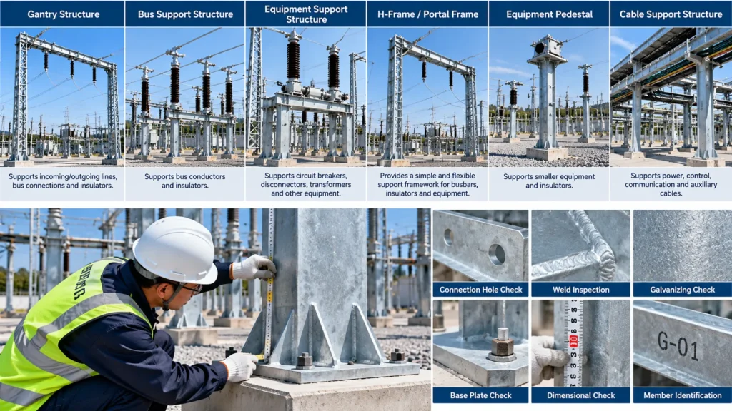
A useful pre-shipment inspection should connect the physical steelwork to the approved drawings and BOM.
Key checks include dimensional verification, member identification, hole location, connection plate orientation, base plate geometry, anchor interfaces, weld condition, galvanizing, quantities, fasteners, packing marks, and drawing revision.
For complex projects, trial assembly requirements should be agreed before production rather than requested after fabrication.
Document review can be equally important.
Depending on the contract, the buyer may require:
- Approved fabrication drawings
- Bill of materials
- Material certificates
- Welding documentation
- Inspection reports
- Galvanizing records
- Dimensional reports
- Packing list
- Structure/member identification schedule
- Nonconformance and repair records where applicable
The exact document package should be defined in the inspection and test plan or purchase specification.
Common Procurement Risks
Several problems recur when substation structures are purchased from drawings that are incomplete or not coordinated with electrical equipment.
Incorrect interface dimensions. Anchor bolts, equipment mounting holes, or base plates do not match civil or equipment drawings.
Uncontrolled drawing revisions. Steel is fabricated against an obsolete layout or equipment interface.
Undefined loads. The fabricator receives geometry but not the approved structural reactions or design basis.
Incomplete coating requirements. The RFQ says “HDG” without defining the applicable standard, inspection criteria, or repair procedure.
Poor piece identification. Similar members arrive on site without a marking system that clearly corresponds to the erection drawings and BOM.
These risks are easier to control before production than during erection.
Questions to Ask a Substation Steel Structure Supplier
Before placing an order, confirm how the supplier will control drawing revisions, material traceability, welding, dimensions, galvanizing, identification, packing, and inspection.
Also establish which party is responsible for structural analysis and which design inputs will be supplied by the EPC, utility, or equipment manufacturer.
If third-party inspection is required, define the hold points and document requirements in the purchase order.
Most importantly, make sure the quotation is based on the same revision of the drawings and technical specification that will govern production.
HSD Steelwork Relevance
HSD Steelwork lists substation gantries, portal frames, H-frames, equipment pedestals, equipment support beams, cable trays, and bus supports among its substation steel structure products for GIS and AIS applications.
The company’s published product information also identifies hot-dip galvanized and duplex coating options and project-specific structural configurations.
For project evaluation, these published capabilities should still be checked against the actual drawings, applicable standard, loading requirements, material specification, inspection plan, and required documentation for the individual project.
What Information Should You Send for a Quotation?
A useful RFQ should contain more than a structure name and voltage class.
Send the available:
- General arrangement and fabrication drawings
- Structure schedule and BOM
- Substation voltage class
- Applicable design and fabrication standards
- Structural loads or approved design criteria
- Steel grades
- Galvanizing or coating specification
- Equipment interface information
- Anchor bolt and foundation details
- Quantity or estimated tonnage
- Inspection and documentation requirements
- Packing requirements
- Destination port or delivery location
- Required project schedule
Better input data reduces technical assumptions during quotation and makes supplier comparisons more meaningful.
FAQ
What are the most common types of substation steel structures?
Common categories include gantries, bus supports, equipment support frames, H-frames, portal frames, equipment pedestals, and cable support structures. The exact terminology varies by utility and project.
What is a substation gantry?
A substation gantry is a steel frame generally formed by vertical supports and horizontal beams. Depending on the electrical design, it can provide attachment points for conductors, insulators, bus connections, and incoming or outgoing circuits.
What is the difference between a bus support and an equipment support?
A bus support primarily supports bus conductors and associated insulators, while an equipment support carries electrical equipment such as breakers, disconnect switches, instrument transformers, or surge arresters. Their loading and interface requirements can therefore be different.
Are all substation steel structures hot-dip galvanized?
Hot-dip galvanizing is widely used for outdoor steelwork, but it should not be assumed for every project. The required corrosion-protection system and applicable coating standard should be specified by the project owner or engineer.
Which galvanizing standard should be specified?
ISO 1461 and ASTM A123/A123M are two relevant standards for fabricated iron and steel articles within their respective scopes. The applicable standard should be determined by the project specification and market requirements.
What information does a manufacturer need before fabrication?
At minimum, the manufacturer needs controlled drawings, material requirements, connection details, applicable standards, coating requirements, and the necessary structural or loading information. Equipment and foundation interfaces should also be coordinated before production.
Can substation structures be selected only by voltage level?
No. Voltage class affects the electrical layout and clearances, but structural selection also depends on conductor arrangement, equipment loads, span, wind and seismic conditions, short-circuit effects where applicable, foundation interfaces, corrosion environment, and project-specific design requirements.
Request a Substation Steel Structure Review
For a project-specific evaluation, send the substation layout, structural drawings, BOM, design standard, loads, steel grade, coating requirement, quantity, inspection requirements, destination, and schedule to HSD Steelwork.
These inputs provide a clearer basis for reviewing the required structure types and preparing a technical and commercial proposal.