


Choosing between a gas-insulated substation (GIS) and an air-insulated substation (AIS) changes more than the switchgear package. It changes how much external steelwork is required, where structural interfaces occur, how loads are transferred, which dimensions are critical, and what procurement teams need to define before fabrication begins.
For steel structure buyers, the practical question is therefore not simply whether GIS or AIS is more compact. It is: what steel structures does each arrangement require, and what must be controlled so the electrical equipment, foundations, bus system, and fabricated steel fit together on site?
Quick Answer
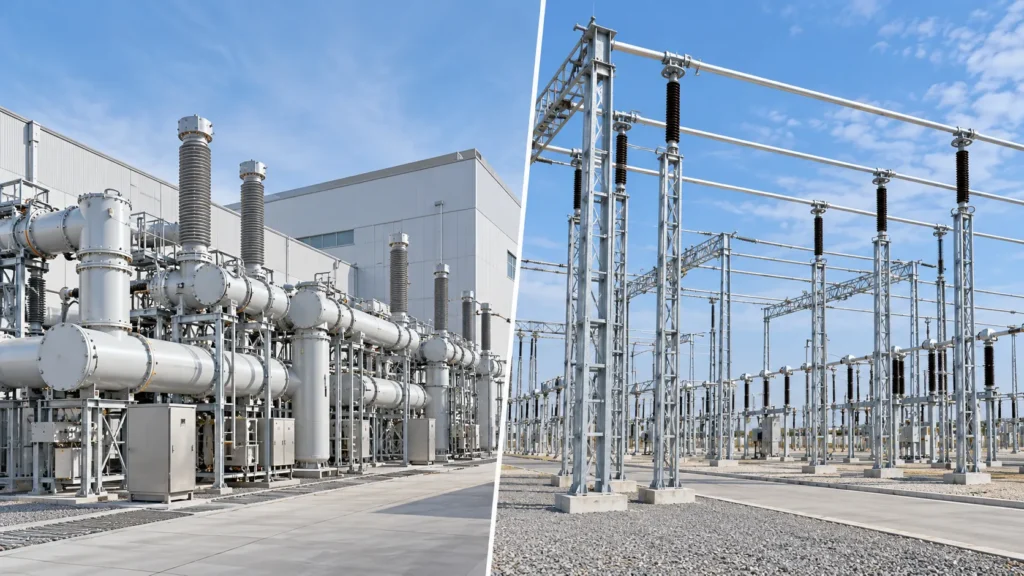
GIS vs AIS substation steel structures differ mainly because GIS encloses energized components inside grounded metal enclosures, while AIS relies on air insulation and therefore needs physical clearances between exposed energized components. GIS projects generally concentrate structural interfaces around GIS equipment supports, buildings, cable or GIL connections, access platforms, and transition points. AIS switchyards typically require more distributed outdoor steelwork, including gantries, bus supports, equipment supports, and termination structures. The correct solution still depends on voltage, bus arrangement, equipment supplier data, wind and seismic criteria, conductor loads, site corrosion conditions, and the governing project standard.
GIS vs AIS: Why the Insulation System Changes the Steelwork
The structural difference begins with the electrical arrangement.
In a GIS, high-voltage conductors and switching components are enclosed within grounded metal housings containing an insulating gas or gas mixture. IEC 62271-203:2022 covers AC gas-insulated metal-enclosed switchgear above 52 kV and recognizes both indoor and outdoor installations.
In an AIS, the insulation between energized parts is primarily atmospheric air. Conductors, disconnectors, circuit breakers, instrument transformers, surge arresters, and bus systems are therefore distributed through an open switchyard with the required electrical clearances.
That difference affects the physical structure of the substation.
GIS often moves a larger share of the equipment into a compact, integrated assembly. AIS spreads equipment across the yard and commonly needs a larger network of independent support structures.
This does not mean every GIS project uses little structural steel or every AIS project uses the same structural arrangement. Voltage level, bay configuration, incoming and outgoing circuits, transformer interfaces, building design, cable or GIL routing, site hazards, and utility practice can substantially change the structural scope.
Typical Steel Structures in a GIS Substation
A GIS project may require fewer conventional open-yard bus supports, but its structural interfaces can be highly equipment-specific.
Common structural items include:
- GIS equipment support frames or embedded support systems
- Building structural steel where the GIS is installed indoors
- Maintenance platforms, stairs, handrails, and access steel
- Cable support and cable tray structures
- GIL or bus duct support frames
- Transformer-to-GIS transition supports
- Outdoor termination gantries where overhead lines connect to GIS
- Equipment support frames for auxiliary outdoor apparatus
- Crane or maintenance-related structural provisions where specified
The key procurement issue is usually interface control.
Support elevations, anchor locations, equipment centerlines, allowable movement, floor or foundation interfaces, and erection tolerances must match the GIS supplier’s approved drawings. A small dimensional mismatch at an equipment interface can create a larger field problem than the same dimensional deviation on a non-critical secondary steel member.
For that reason, fabrication should not begin from an early general arrangement drawing when critical equipment interfaces are still changing.
Typical Steel Structures in an AIS Substation
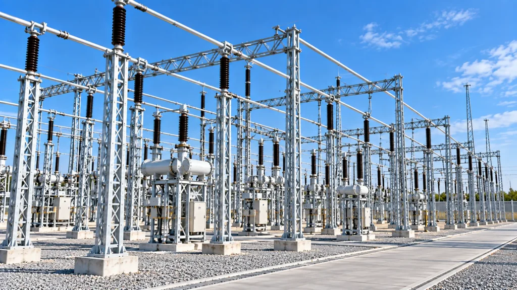
AIS normally has more visible and distributed steel structures because electrical equipment and conductors are supported separately throughout the switchyard.
Typical AIS steelwork includes:
- Line entrance and termination gantries
- Bus support structures
- Equipment support structures
- Disconnect switch supports
- Instrument transformer supports
- Surge arrester supports
- Insulator support frames
- Portal frames and H-frames
- Cable support structures
- Equipment platforms and access steel
IEEE 605-2023 describes rigid and strain bus arrangements in air-insulated substations and notes that bus design calculations are used to determine forces acting on bus structures and the number of mounting structures required.
This is important for procurement: an AIS bus support is not simply a fabricated column selected by height. The structural engineer needs the conductor arrangement, span, equipment and insulator information, wind criteria, fault-related forces where applicable, thermal effects, and other project load requirements before the support can be properly designed.
GIS vs AIS Substation Steel Structures at a Glance
| Design or Procurement Issue | GIS | AIS |
| Structural distribution | More concentrated around equipment, buildings, transitions, and access systems | More distributed throughout the outdoor switchyard |
| Conventional bus support steel | Often reduced where bus conductors are enclosed within GIS | Commonly required for exposed rigid or strain bus systems |
| Gantries | May be required at overhead-line or transition interfaces | Common for line entrances, terminations, and some bus arrangements |
| Equipment supports | Equipment-specific supports and frames | Numerous individual outdoor equipment supports are common |
| Dimensional interfaces | Strong dependence on GIS vendor interface drawings | Strong dependence on yard layout, equipment footprints, conductor elevations, and bus geometry |
| Environmental exposure | Indoor GIS structural steel may have reduced direct weather exposure; outdoor interfaces remain exposed | Most switchyard steel is directly exposed to the site environment |
| Field erection | Concentrated interfaces can demand tight coordination | Larger number of repeated structures can increase erection and alignment work |
| Expansion planning | Depends heavily on GIS arrangement and reserved interfaces | Additional bays may require yard space plus new supports, gantries, and bus extensions |
The table describes common tendencies, not universal design rules. The project layout and equipment supplier documentation remain controlling inputs.
Structural Loads Must Come Before Member Selection
Whether the project uses GIS or AIS, steel section selection should follow the project load definition rather than precede it.
Depending on the structure, relevant inputs can include:
- Self-weight and permanently attached equipment
- Equipment operating or maintenance loads
- Conductor or bus loads
- Wind loads
- Seismic actions
- Ice loads where applicable
- Short-circuit-related forces
- Cable or conductor tensions
- Thermal movement
- Construction and maintenance loads
- Loads transferred through equipment interfaces
- Project-specific load combinations
ASCE’s second edition of Substation Structure Design Guide, Manual of Practice 113 addresses outdoor electrical substation structures and foundations and includes updated treatment of hazards, anchor bolts, seismic design, foundations, and short-circuit forces.
For buyers, the lesson is simple: do not issue an RFQ with only a structure height and a sketch if the supplier is expected to provide structural design.
The RFQ should identify the governing design basis and provide the loads or the information needed to establish them.
GIS Projects Put More Pressure on Interface Accuracy
GIS steelwork may be less repetitive than a large AIS yard, but the connection between steel and equipment can be more tightly controlled.
Before fabrication, confirm at least:
- Approved equipment centerlines and elevations.
- Anchor bolt coordinates and bolt sizes.
- Base plate and embedded plate interfaces.
- Equipment loads and load directions.
- Allowable tolerances at connection points.
- Required movement or expansion provisions.
- Access and maintenance envelopes.
- Cable, GIL, bus duct, and piping conflicts.
- Final equipment revision status.
A fabrication drawing can be internally correct and still fail in the field if it was produced from an obsolete vendor drawing.
A practical document-control system should therefore identify the exact GIS vendor drawing revision used for each structural interface.
AIS Projects Require Strong Control of Repetition and Alignment
AIS structures are often repeated across several bays. Repetition can improve fabrication efficiency, but it also makes a systematic dimensional error more expensive.
Bus support centerlines, insulator mounting plates, equipment elevations, hole patterns, gantry geometry, and anchor bolt layouts should be checked against the approved substation layout before mass fabrication.
For repeated structures, buyers should consider approving a first article, trial assembly, template, or other dimensional verification method before releasing the entire production quantity.
The exact method depends on the structure and project specification, but the objective is the same: detect a repeated interface error before it reaches dozens of fabricated assemblies.
Fabrication Tolerances: Do Not Use One Number for Every Interface
A common procurement mistake is to specify a general fabrication tolerance and assume it covers every structural requirement.
It may not.
The acceptable tolerance for a non-critical brace is not necessarily suitable for:
- GIS equipment connection points
- Insulator mounting holes
- Base plate anchor patterns
- Bus support elevations
- Equipment support centerlines
- Flange connections
- GIL or bus duct interfaces
The purchaser should identify critical dimensions on approved drawings and specify how they will be inspected.
Where equipment supplier tolerances are more restrictive than general steel fabrication tolerances, the interface requirement should be resolved before production.
Hot-Dip Galvanizing and Corrosion Protection
Outdoor AIS steel structures are commonly exposed continuously to rain, humidity, airborne contaminants, and other site-specific corrosive conditions. Outdoor GIS transition steelwork can face the same environment.
Hot-dip galvanizing is therefore frequently specified for substation structural steel.
ISO 1461:2022 defines general properties and test methods for batch hot-dip galvanized coatings on fabricated iron and steel articles. Its scope includes coating appearance, thickness, acceptance inspection, sampling, renovation, and declaration of compliance.
However, writing “galvanized according to ISO 1461” on a purchase order does not replace project-specific corrosion decisions.
The purchaser should still define:
- Applicable galvanizing or coating standard
- Required coating system
- Site corrosivity or environmental conditions
- Any project-specific coating thickness requirement
- Areas requiring masking or special treatment
- Treatment of damaged coating
- Duplex coating requirements, if any
- Inspection and reporting requirements
Fabrication details also need to be compatible with galvanizing. Venting, drainage, enclosed spaces, overlapping surfaces, distortion risk, and component size should be considered before fabrication is released.
What Should Be Inspected Before Shipment?
Inspection should verify more than whether the steel “looks correct.”
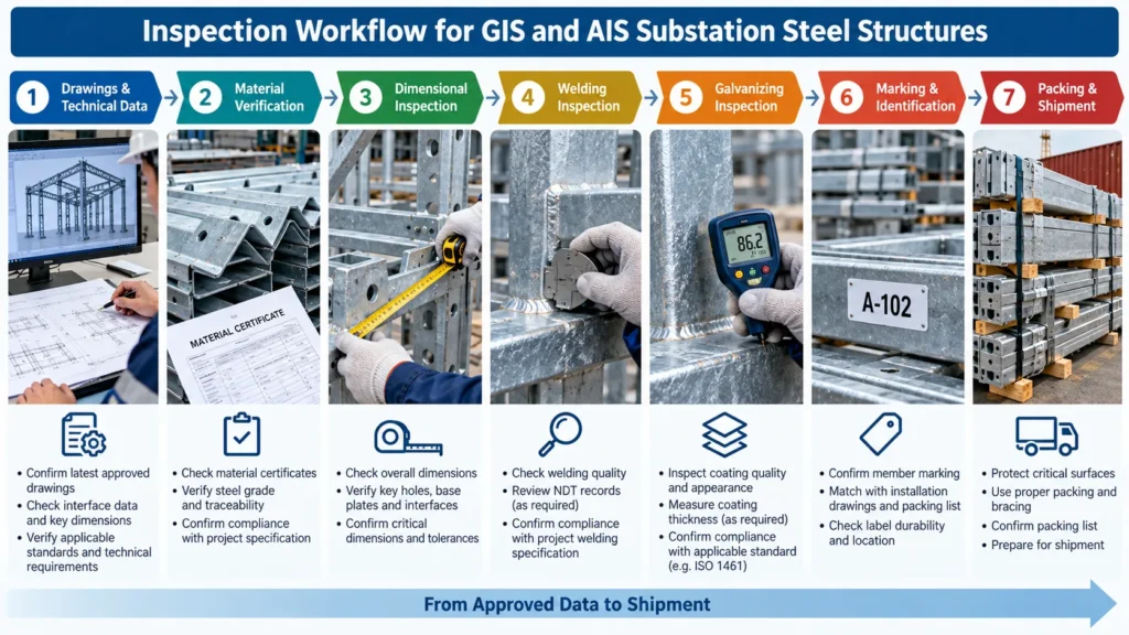
A practical inspection plan can include:
Material verification: Check material certificates against the approved material specification and traceability requirements.
Dimensions: Verify overall dimensions plus critical hole patterns, mounting plates, base plates, connection geometry, and equipment interface points.
Welding: Confirm welding documentation and inspection requirements specified by the project. Acceptance criteria should come from the applicable code and project specification.
Trial assembly or fit-up: Use where required to confirm critical interfaces or repeated assemblies.
Galvanizing or coating: Inspect according to the specified coating standard and project requirements. ISO 1461:2022 includes acceptance inspection and coating thickness provisions for batch hot-dip galvanized articles.
Marking: Confirm piece marks correspond to erection drawings and packing lists.
Packing: Protect plates, threads, connection surfaces, and projecting parts from transport damage. Packing should also support efficient identification at site.
Common Procurement Risks
1. Releasing Steel Before Equipment Drawings Are Frozen
This is especially risky for GIS equipment supports and transition structures.
Control: Establish an approved interface-drawing register and release status before fabrication.
2. Missing AIS Bus Loads
A general arrangement drawing does not provide all structural loads.
Control: Coordinate bus design, insulator data, conductor geometry, environmental criteria, and fault-related load requirements with the responsible electrical and structural engineers.
3. Treating All Supports as Interchangeable
Two supports with similar heights can have different base reactions, mounting interfaces, stiffness requirements, or equipment loads.
Control: Use unique structure marks tied to approved drawings and load schedules.
4. Ignoring Galvanizing During Detailing
Poor venting or drainage details can create manufacturing and coating problems.
Control: Review fabrication details for galvanizing suitability before production.
5. Incomplete Shipment Identification
Large AIS projects may contain many visually similar frames and members.
Control: Coordinate piece marking, packing lists, bundle identification, and erection drawings before dispatch.
Documents to Request From a Substation Steel Structure Supplier
The required document package should be agreed in the purchase specification. Depending on scope, it may include:
- Approved shop or fabrication drawings
- General arrangement drawings
- Bill of materials
- Structural calculations, where included in supplier scope
- Material certificates
- Welding documentation required by the project
- NDT reports where specified
- Dimensional inspection records
- Galvanizing or coating inspection records
- Trial assembly records where required
- Bolt and fastener documentation
- Packing list
- Piece-mark schedule
- Inspection release documentation
Do not assume every supplier provides the same document package. Define deliverables, approval stages, and hold or witness points before the purchase order is finalized.
Questions to Ask a GIS or AIS Steel Structure Supplier
Before awarding the steel package, ask:
- Which design standard and load combinations will be used?
- Which loads must be provided by the purchaser or equipment vendor?
- How are GIS vendor interfaces or AIS bus interfaces controlled?
- Which dimensions are treated as critical inspection points?
- How are material heat numbers or other traceability identifiers maintained?
- What welding and NDT documentation can be supplied?
- How is galvanizing inspected?
- Can repeated or critical assemblies be trial-fitted when the project requires it?
- How are piece marks linked to erection drawings and packing lists?
- Which drawings must receive purchaser approval before fabrication starts?
These questions are more useful than asking only for unit price per ton because they expose interface, quality, and field-installation risks before production.
Information to Include in an RFQ
For a useful quotation, provide as much of the following as available:
- Project country and site location
- GIS or AIS arrangement
- Voltage class
- Single-line diagram where relevant
- Substation general arrangement
- Equipment supplier drawings
- Structure drawings or design scope
- Design standards
- Wind, seismic, ice, and other environmental criteria
- Equipment and conductor loads
- Steel grade
- Bolting requirements
- Welding requirements
- Galvanizing or coating specification
- Required inspections and NDT
- Documentation requirements
- Quantity
- Packing requirements
- Delivery destination
- Required project schedule
If information is still preliminary, identify it as preliminary rather than allowing the steel supplier to treat it as approved-for-fabrication data.
HSD Steelwork Relevance
HSD Steelwork lists substation gantries and structures among its power infrastructure products, including gantries, portal frames, H-frames, equipment pedestals, equipment support beams, cable trays, and bus supports for GIS and AIS applications.
For a project-specific review, the steel package still needs to be evaluated against the purchaser’s drawings, loads, applicable standards, coating specification, inspection requirements, and documentation requirements.
See HSD Steelwork’s substation gantries and steel structures product information for the currently published scope.
Request a Project-Specific Steel Structure Review
GIS and AIS projects create different structural interfaces, but both depend on accurate input data before steel fabrication begins.
For a quotation or technical review, send the substation layout, GIS/AIS arrangement, applicable standards, equipment interface drawings, design loads, steel grade, coating specification, quantities, inspection requirements, packing requirements, destination, and required schedule.
This gives the supplier enough information to identify the structural scope and clarify missing inputs before pricing or fabrication.
FAQ
Does a GIS substation require less structural steel than an AIS substation?
Often, GIS reduces the amount of distributed outdoor bus-support steel because much of the high-voltage equipment is enclosed in a compact assembly. However, the total steel quantity depends on the GIS building, equipment supports, GIL or cable interfaces, termination gantries, platforms, and project layout. It should be determined from the actual design rather than assumed from substation type alone.
Why does AIS need so many support structures?
AIS uses air as the primary external insulation between exposed energized components. The equipment and conductors must therefore be arranged with appropriate electrical clearances and physically supported throughout the switchyard, creating demand for bus supports, equipment supports, gantries, and related steelwork.
Are GIS steel structure tolerances tighter than AIS tolerances?
Not universally. GIS projects can have highly sensitive equipment interface dimensions, while AIS projects can also require precise bus, insulator, equipment, and anchor alignment. Critical tolerances should be taken from the governing design and equipment interface requirements rather than assigned solely according to GIS or AIS type.
What standard applies to GIS above 52 kV?
IEC 62271-203:2022 covers AC gas-insulated metal-enclosed switchgear for rated voltages above 52 kV. Project specifications may also reference additional IEC, IEEE, structural, seismic, material, welding, and coating standards.
What information is needed to design an AIS bus support?
Typical inputs include bus arrangement, conductor type and geometry, insulator data, support spacing, equipment elevations, environmental loads, fault-related forces where applicable, material requirements, and the governing design criteria. The responsible engineer should define the complete project load basis.
Should substation steel structures be hot-dip galvanized?
Hot-dip galvanizing is commonly specified for outdoor substation steel, but the appropriate corrosion protection system depends on the project environment and specification. ISO 1461:2022 provides requirements and test methods for batch hot-dip galvanized coatings on fabricated iron and steel articles.