


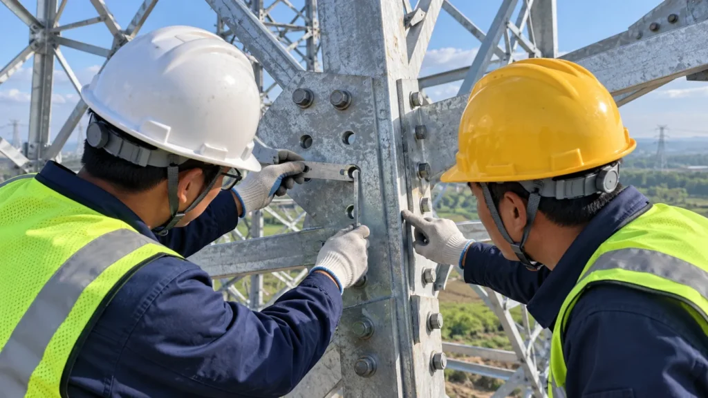
A transmission tower erection crew reaches a connection point, positions the galvanized angle steel members, and discovers that the bolt holes do not line up. The drawings appear correct, the members have identification marks, and the bolts are available. Yet the connection cannot be completed without further investigation.
This situation can delay erection, increase labor costs, and create disputes between the fabrication supplier and installation contractor.
The key is to identify whether the mismatch originates from fabrication, incorrect member selection, foundation geometry, assembly sequence, transportation damage, or uncontrolled dimensional changes.
Understanding the common causes of transmission tower hole misalignment helps EPC contractors, utilities, and manufacturers prevent avoidable site rework.
Quick Answer: What Causes Transmission Tower Hole Misalignment?
Transmission tower hole misalignment occurs when the bolt holes of connecting members cannot be brought into the required position under the approved assembly conditions. Common causes include incorrect hole drilling or punching, fabrication dimensional errors, member deformation, inaccurate foundation anchor-bolt positioning, wrong member identification, and improper erection sequence. Galvanizing distortion or handling damage may also contribute. Not every alignment problem is a manufacturing defect. The correct response is to verify drawings, member marks, connection orientation, measured dimensions, and foundation geometry before modifying any steel component. Unapproved hole enlargement, flame cutting, or forced assembly may compromise the designed connection and should not be used as routine corrective measures.
1. Incorrect Hole Positioning During Fabrication
Hole positioning errors are among the most direct causes of transmission tower connection problems.
Tower members are manufactured according to approved fabrication drawings that define hole coordinates, pitch, edge distances, connection geometry, and member orientation.
A small error in one member may become visible only when several components are connected during erection.
Common fabrication-related problems include:
- Incorrect CNC drilling or punching program data.
- Wrong drawing revision used for production.
- Inaccurate member positioning or datum selection.
- Incorrect hole pitch or edge distance.
- Mixing members from different tower configurations.
- Failure to verify critical dimensions after machining.
For example, a hole group manufactured from the wrong reference end may have correct internal spacing but an incorrect position relative to the member ends.
How to detect the problem: Measure the hole center positions against the approved drawing using defined datums. Check the entire hole pattern rather than measuring only one hole.
How to prevent it: Use controlled drawing revisions, verified machining programs, first-piece inspection, and documented dimensional checks.
2. Incorrect Member Length or Connection Geometry
A tower member can have correctly spaced holes and still fail to fit if its overall length or connection geometry is incorrect.
Typical causes include inaccurate cutting, incorrect end preparation, wrong connection plate positioning, or an incorrect member designation.
The mismatch may appear at a distant connection rather than at the member where the dimensional error originated.
For example, if a diagonal brace is fabricated with an incorrect effective connection length, the crew may align one end but be unable to align the other end without introducing force.
Inspection actions:
- Confirm the member mark and drawing revision.
- Measure the overall length and relevant connection dimensions.
- Check hole-to-end distances and the hole group orientation.
- Compare the member with the approved fabrication details.
- Record the actual deviation before deciding on corrective action.
The correct assessment depends on the project-specific tolerances and the structural function of the connection.
3. Incorrect Member Identification or Installation Orientation
Not every fit-up problem comes from inaccurate manufacturing.
Transmission towers may contain many visually similar angle steel members, especially within bracing systems and repeated tower panels.
Members with similar lengths or hole patterns can be confused during sorting or erection.
Common examples include installing a member:
- At the wrong tower elevation.
- On the wrong face of the tower.
- In the reverse orientation.
- From a different tower type or extension configuration.
- With an incorrect connection plate or splice component.
A crew may initially assume that the holes were manufactured incorrectly when the actual issue is that the wrong member has been selected.
Prevention Through Marking and Packing
Each member should be identifiable through a controlled marking system linked to the approved bill of materials and erection drawings.
Package identification should support practical site sorting by tower type, section, or erection sequence where specified.
Before investigating a suspected fabrication defect, the crew should verify the member mark, tower location, orientation, and mating parts.
4. Foundation Anchor Bolt and Stub Setting Errors
The foundation-to-tower interface is a critical starting point for dimensional accuracy.
For towers with embedded stubs, anchor bolts, or base plates, incorrect setting-out can affect the geometry of the entire lower structure.
Potential causes include:
- Incorrect anchor-bolt spacing.
- Stub inclination or orientation errors.
- Incorrect foundation elevation.
- Base geometry inconsistent with approved setting-out data.
- Survey or measurement errors.
- Movement during concrete placement.
A foundation geometry error can create cumulative fit-up problems as the tower structure rises.
What Should Be Checked?
Before erection, the responsible team should verify the as-built foundation or stub geometry against the approved design and survey control.
Checks may include horizontal positioning, relative elevations, orientation, spacing, and relevant interface dimensions.
Where a deviation exists, the project engineer should assess its effect before erection continues.
Do not assume that upper-level hole misalignment can be corrected by pulling the tower structure into position.
5. Improper Erection Sequence and Temporary Alignment
Transmission tower erection depends on the correct assembly sequence and temporary stability.
Even correctly fabricated members may appear misaligned when adjacent connections are fully tightened too early or the structure has not reached its intended geometry.
Possible causes include:
- Premature final tightening of bolts.
- Incorrect installation sequence.
- Missing temporary bracing.
- Inadequate alignment of tower panels.
- Uncontrolled lifting or temporary loads.
- Failure to follow the approved erection method.
For example, fully tightening one connection before adjacent braces are installed may restrict the movement required to complete the next connection.
The erection procedure should specify when connections may remain temporarily adjustable and when final tightening is required.
Important: Loosening connections or changing temporary supports must follow the approved erection method and temporary stability requirements. It should not be improvised on an unsupported structure.
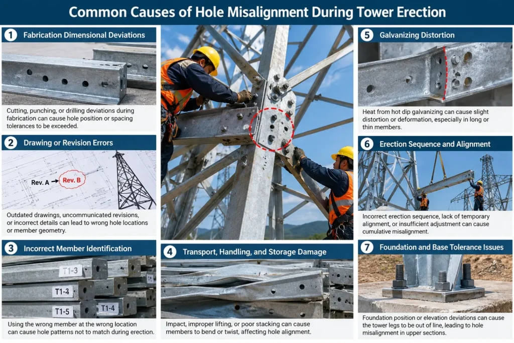
6. Galvanizing Distortion and Dimensional Changes
Hot-dip galvanizing provides corrosion protection, but fabrication geometry and thermal processing must be considered together.
Some welded assemblies, thin components, or structures containing residual stresses may experience distortion during galvanizing.
For typical individual tower angle members, the risk depends on member geometry, fabrication history, and processing conditions. It should not automatically be treated as the main cause of a hole mismatch.
Possible concerns include:
- Bowing or twisting of members.
- Distortion of welded connection assemblies.
- Changes in fit-up caused by existing residual stresses.
- Excess zinc accumulation interfering with bolt insertion or mating surfaces.
The distinction between a dimensional hole-position error and a local coating obstruction is important.
A hole that is correctly positioned but obstructed by zinc requires a different assessment from a hole drilled at an incorrect coordinate.
The applicable galvanizing specification, coating repair rules, and project requirements should govern inspection and corrective work.
7. Transportation, Handling, and Storage Damage
Transmission tower members can be damaged after leaving the fabrication plant.
Improper lifting, inadequate support, excessive stacking loads, or rough handling may bend or twist components.
Long, relatively slender members deserve particular attention during loading, unloading, and site storage.
Damage can also occur when bundled components are dragged or lifted from unsuitable points.
How to Identify Handling Damage
Inspect for visible bending, twisting, impact marks, local deformation, and damaged connection areas.
Compare the suspect member with its approved dimensions and available factory inspection records.
Where transport damage is suspected, photographs from packing, loading, receiving, and unloading can help establish when the condition occurred.
A packing list alone does not prove that members arrived without damage.
8. Missing Trial Assembly or Inadequate Fit-Up Verification
Trial assembly is a useful manufacturing quality-control method for identifying connection and geometry problems before repetitive production or shipment.
Depending on project requirements, trial assembly may cover a complete representative tower, a tower section, or selected critical connections.
It can reveal issues such as incorrect member orientation, hole pattern mismatch, drawing inconsistencies, and accumulated dimensional errors.
However, trial assembly is not a substitute for production inspection.
A successful trial assembly does not automatically prove that every later-produced member is dimensionally correct.
What Should Trial Assembly Records Include?
Useful evidence may include:
- Identification of the tower type and assembly scope.
- Approved drawings and revision numbers.
- Member identification and inspection records.
- Connection fit-up observations.
- Dimensional nonconformities and corrective actions.
- Reinspection results and authorized acceptance.
The buyer should agree on the required trial assembly scope, acceptance criteria, and documentation before manufacturing begins.
9. How Can Site Teams Identify the Actual Cause?
When a hole mismatch is found, the most effective approach is to isolate the problem before making changes.
The following table provides a practical starting point.
| Site Observation | Possible Cause | First Verification |
| One member does not fit at either end | Wrong member or hole-position error | Member mark, orientation, hole coordinates |
| One end fits but the opposite end does not | Incorrect length, geometry, or panel alignment | Overall length and assembly geometry |
| Multiple connections misalign near the tower base | Foundation or stub-setting error | As-built foundation survey |
| Holes align before tightening but shift afterward | Assembly sequence or structural restraint | Approved erection method and connection sequence |
| Member is visibly bent or twisted | Fabrication distortion or handling damage | Straightness checks and receiving records |
| Bolt cannot pass through otherwise aligned holes | Zinc obstruction, burr, hole-size issue, or local offset | Hole condition, dimensions, and coating |
| Similar mismatch repeats across multiple towers | Drawing, programming, or production-system issue | Drawing revision and manufacturing inspection records |
These are diagnostic indicators, not final determinations. More than one cause can be present.
10. Why Forced Assembly and Unauthorized Hole Enlargement Are Risky
A site crew may be tempted to use excessive force, enlarge holes, or cut away material to make a connection fit.
These actions can conceal the underlying dimensional problem.
Depending on the connection design, uncontrolled modifications may affect bolt bearing, edge distance, net section, load transfer, fatigue performance, or corrosion protection.
The fact that a bolt can be inserted after modification does not prove that the connection remains structurally acceptable.
A controlled response should include a documented nonconformance, measured deviation, engineering evaluation, approved repair or replacement decision, and verification of the completed corrective action.
Any field drilling, reaming, hole enlargement, or other structural modification should be specifically authorized under the project requirements.
11. How Manufacturers Can Reduce Hole Misalignment Before Shipment
Effective prevention begins before the first tower member is fabricated.
The manufacturer and buyer should establish a controlled process covering drawings, machining, inspection, identification, and shipping.
| Manufacturing Stage | Recommended Control | Evidence to Request |
| Engineering release | Verify approved drawings and revisions | Drawing register |
| Material preparation | Verify member designation and dimensions | Material and cutting records |
| Hole machining | Verify program, datum, pitch, and hole location | First-piece and dimensional inspection reports |
| Fabrication | Check length, straightness, and connection geometry | Fabrication inspection records |
| Trial assembly | Verify selected critical fit-up interfaces | Trial assembly report, where required |
| Galvanizing | Inspect coating and relevant post-process condition | Galvanizing inspection records |
| Marking and packing | Match physical members with approved BOM | Marking records and packing lists |
| Shipment release | Confirm outstanding nonconformities are resolved | Final inspection and release documentation |
These controls reduce risk when properly implemented, but no inspection process eliminates every possible field issue.
12. What Should EPC Contractors Ask a Tower Manufacturer?
During supplier qualification, procurement teams should look beyond the manufacturer’s stated machining capability.
Ask how drawing revisions are controlled, how CNC programs are verified, and which dimensions are checked on first-piece and production inspections.
Clarify whether trial assembly is required, how nonconforming members are handled, and how individual parts remain identifiable after galvanizing.
The contract should also define how site-discovered mismatches are reported, investigated, and resolved, including responsibility for technical disposition and replacement arrangements.
A documented process is more useful than a general statement that all holes will fit perfectly.
13. What Information Should Be Included in a Hole Misalignment Report?
A useful site nonconformance report should allow the manufacturer and engineering team to identify the exact connection and assess the deviation without relying on descriptions such as “holes do not fit.”
Include the tower number and type, erection elevation, member marks, drawing revision, connection reference, hole dimensions, measured offset, and photographs with a measurement reference.
Record the installation sequence and whether the structure was temporarily supported or partially tightened when the mismatch was observed.
If a replacement or modification is proposed, attach the engineering disposition and inspection requirements.
This evidence helps distinguish an isolated damaged member from a systematic production or design problem.
14. How HSD Steelwork Can Support Tower Procurement Discussions
For transmission tower procurement, the quality of fabrication information and the clarity of inspection requirements are important parts of supplier evaluation.
HSD Steelwork can be contacted to discuss a project RFQ and the required scope of tower fabrication, dimensional verification, marking, packing, and quality documentation.
Specific production capabilities, trial assembly arrangements, inspection services, tolerances, and deliverables should be confirmed against HSD’s current technical and commercial proposal.
Request a Tower Fabrication and Quality Review
To prepare a meaningful technical inquiry, provide the approved tower drawings, tower types, applicable design and fabrication standards, material grades, hole and connection requirements, quantities, inspection expectations, delivery destination, and target schedule.
For an existing erection problem, include the measured mismatch and supporting site records.
Contact HSD Steelwork: HSD Steelwork website.
Frequently Asked Questions
1. Can bolt holes be enlarged on site if tower members do not fit?
Only when an authorized engineering disposition permits the modification. The engineer must assess the connection design, remaining edge distances, bolt requirements, and applicable project specifications before work proceeds.
2. Can hot-dip galvanizing cause tower bolt holes to become misaligned?
Galvanizing-related distortion may affect some components, while zinc accumulation can interfere with bolt insertion. However, galvanizing should not be assumed to be the cause without dimensional and visual inspection.
3. How can buyers tell whether a hole mismatch is a factory defect?
Compare the actual member dimensions and hole coordinates with the approved fabrication drawings. Also verify member identity, orientation, foundation geometry, and erection conditions before assigning responsibility.
4. Does trial assembly guarantee that all tower members will fit on site?
No. Trial assembly can identify important design and fabrication issues within its tested scope, but later production variation, transport damage, foundation errors, and erection practices can still create fit-up problems.
5. What should workers do when bolts cannot be inserted during erection?
Stop attempts to force the connection, maintain structural stability, confirm member identification and orientation, and measure the mismatch. Escalate the issue through the approved site quality and engineering process.
6. Which factory records are useful when investigating repeated hole misalignment?
Approved drawings, revision registers, CNC program verification records, first-piece inspection reports, dimensional inspection reports, trial assembly records where applicable, and nonconformance reports can help trace recurring errors.
7. Who is responsible for correcting hole misalignment during tower erection?
Responsibility depends on the established root cause and contract terms. The cause may involve design, fabrication, foundation construction, handling, or erection. The project should use documented evidence and an authorized technical disposition rather than assuming responsibility from the location where the problem was discovered.