


Two transmission lines may operate at the same nominal voltage yet use towers with noticeably different heights, crossarm arrangements, and steel quantities. Conversely, a lower-voltage line crossing a deep valley may require taller structures than a higher-voltage line on relatively flat ground.
This creates a practical challenge for utilities and EPC contractors: voltage level is essential when planning a transmission line, but it is not enough to specify a tower or prepare a reliable manufacturing quotation.
Understanding how electrical clearances, conductor arrangements, structural loads, and site conditions interact helps project teams develop more complete tower specifications and avoid costly assumptions during procurement.
Quick Answer: How Does Voltage Level Affect Transmission Tower Height?
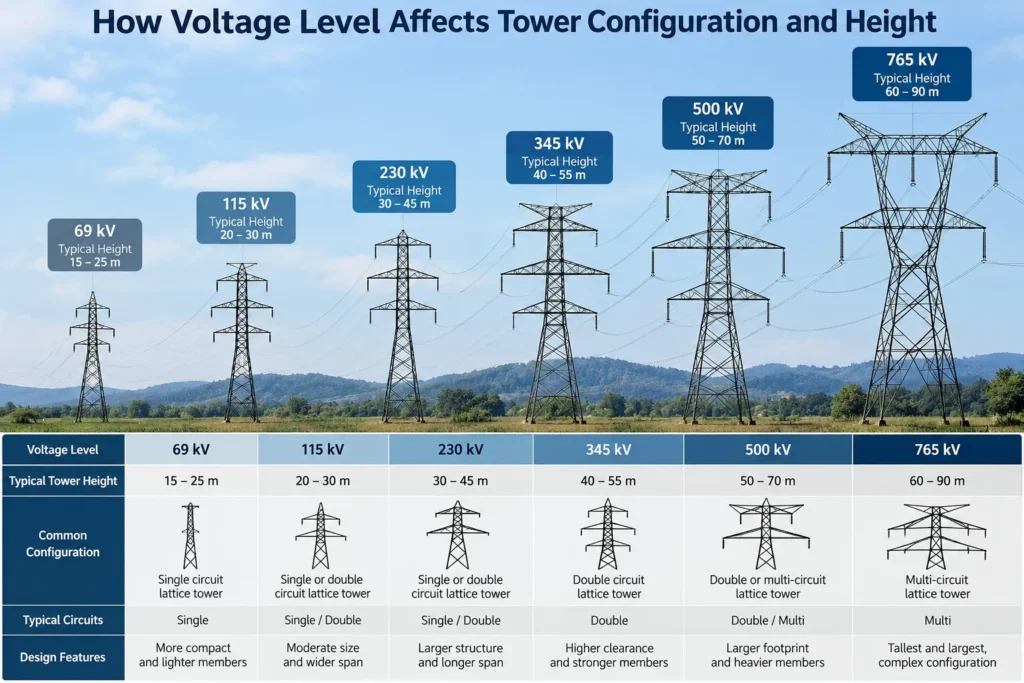
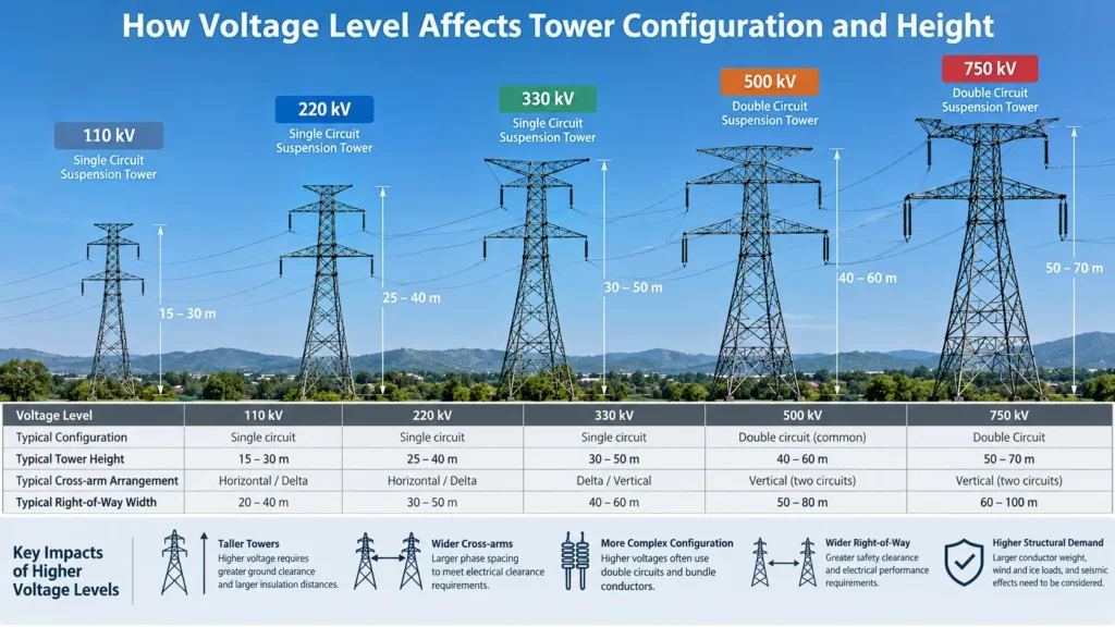
Voltage level affects transmission tower configuration and height primarily through insulation coordination, required electrical clearances, and conductor arrangement. Higher-voltage systems generally require greater separation between energized components and grounded steelwork, often leading to larger crossarms, longer insulation assemblies, or taller structures. However, voltage alone does not determine tower height. Ground clearance, conductor sag, span length, terrain, wind and ice loading, circuit configuration, and applicable standards also influence the final geometry. Tower dimensions should therefore be established through project-specific electrical and structural design rather than selected from a fixed height chart based only on nominal voltage.
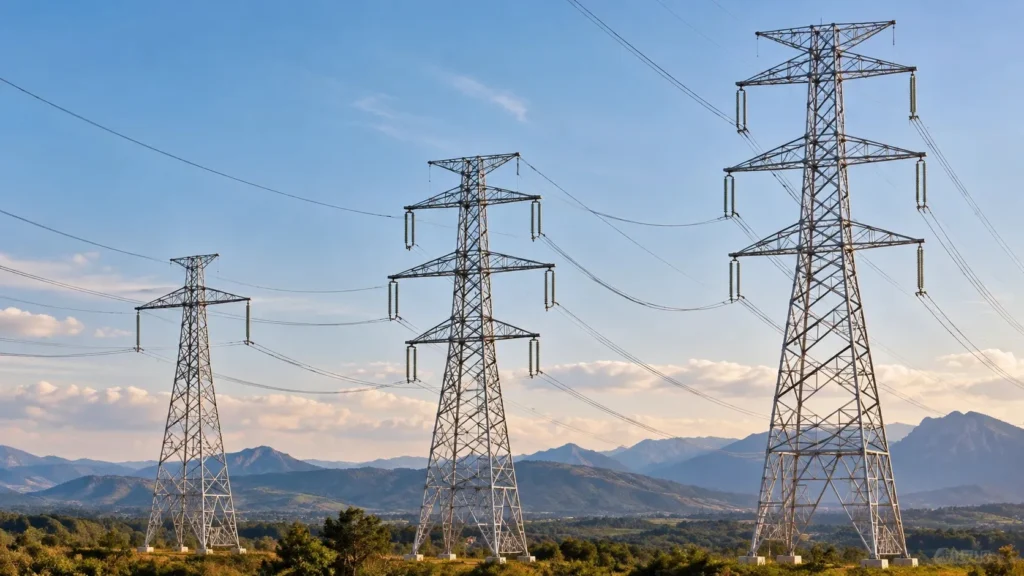
1. Why Does Voltage Level Change Transmission Tower Configuration?
Transmission towers must support conductors while maintaining safe electrical separation under the operating and environmental conditions defined for the line.
As system voltage increases, electrical insulation and clearance requirements generally become more demanding.
These requirements affect several parts of the structure:
- Conductor-to-tower clearance: The required separation between energized conductors or fittings and grounded steelwork.
- Phase-to-phase clearance: The spacing needed between conductors belonging to different phases.
- Insulator arrangement: The insulation assembly length, orientation, and movement envelope.
- Crossarm geometry: The location of conductor attachment points relative to the tower body.
- Tower body dimensions: The geometry needed to accommodate conductor positions and structural loads.
The actual requirements depend on the highest voltage for equipment, insulation coordination, environmental conditions, and the governing line design rules. Nominal voltage should not be treated as a complete clearance specification.
For example, a higher-voltage line may require wider crossarms to maintain adequate phase separation. Depending on the conductor arrangement, it may instead use a greater vertical separation between attachment points.
Both approaches can affect tower weight, fabrication complexity, transportation, and erection.
2. How Does Tower Configuration Typically Change Across Voltage Classes?
Different voltage classes commonly use different conductor arrangements and structural proportions. However, no single tower configuration is mandatory for a given voltage.
The following comparison is illustrative, not a dimensional design table.
| Nominal voltage | Common design considerations | Possible configuration implications |
| 66–110 kV | Electrical clearance, circuit count, right-of-way | Relatively compact lattice configurations may be practical |
| 132–138 kV | Increased clearance needs, conductor arrangement, span geometry | Larger attachment spacing or crossarms may be needed |
| 220–230 kV | Insulation coordination, phase spacing, conductor loads | Wider or taller lattice configurations may be selected |
| 345–400 kV | Larger electrical envelopes, bundle arrangements, loading | Substantial crossarm and tower-body geometry may be required |
| 500 kV and above | EHV insulation coordination, conductor bundles, environmental effects | Larger structural arrangements and more demanding interface requirements are common |
These are general planning observations. Actual tower dimensions may differ substantially between projects in the same voltage class.
Single-Circuit vs. Double-Circuit Towers
Circuit count can change tower configuration as much as voltage level.
A single-circuit three-phase line generally has three phase positions. A double-circuit line typically has six phase positions, although each phase may use one conductor or a bundle of subconductors.
A double-circuit tower may require additional attachment levels, a wider configuration, or both.
For procurement teams, circuit count should always be specified separately from nominal voltage.
3. Does Higher Voltage Always Mean a Taller Transmission Tower?
No. Higher voltage generally increases the electrical space that must be accommodated, but it does not establish the total tower height.
Tower height is influenced by the relationship between conductor attachment elevation, sag, and the required clearance beneath the conductor.
The main variables include:
Ground clearance. Conductors must maintain the clearance required by the applicable regulations and project design criteria over roads, land, buildings, waterways, and other obstacles.
Conductor sag. Conductors change position with temperature, mechanical tension, loading, and time-dependent behavior. The controlling sag case affects the required attachment elevation.
Span length. Longer spans can create greater sag or different loading requirements, depending on the conductor and tension design.
Terrain. Uneven ground, valleys, slopes, and crossing obstacles can require special tower extensions or structures.
Insulator geometry. Suspension and tension assemblies place conductors at different positions relative to their attachment points.
Shielding and lightning protection. Overhead ground wires or optical ground wires may require additional structure above the phase conductors.
Consequently, a tower height comparison is meaningful only when the design conditions are defined.
4. How Do Conductor Clearances Affect Crossarm Design?
Crossarms position conductors away from the tower body and from other energized conductors.
Their dimensions must account for electrical and mechanical conditions, including conductor and insulator movement.
For suspension towers, wind can displace insulator strings and conductors toward the tower body. Designers therefore assess the applicable clearance cases rather than relying on the static arrangement shown in a drawing.
Crossarm design may also be affected by:
- Phase arrangement and conductor bundle geometry
- Suspension or tension insulator assemblies
- Jumper movement at angle and dead-end structures
- Maintenance and live-line working requirements, where applicable
- Structural strength and deflection limits
For tower manufacturers, these decisions translate into steel member lengths, connection geometry, bolt arrangements, and fabrication tolerances.
A change to crossarm geometry after fabrication drawings have been released may require revisions to multiple connected members, not simply one crossarm component.
5. Horizontal, Vertical, and Delta Conductor Arrangements
Transmission line designers can use different phase arrangements to satisfy electrical, structural, and corridor requirements.
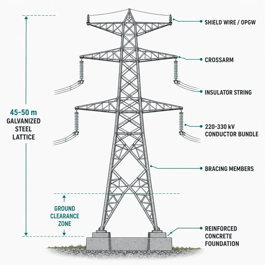
Horizontal arrangement
Places phase conductors at approximately the same elevation. It may reduce the number of phase attachment levels while requiring a wider crossarm and corridor envelope.
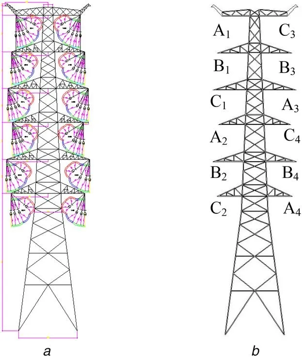
Vertical arrangement
Uses multiple conductor attachment elevations. It may help accommodate circuits within a narrower corridor, although it can increase tower height.
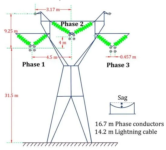
Delta arrangement
Positions the three phase conductors in a triangular pattern. Its suitability depends on electrical clearances, loading, and line layout.
The arrangement is not determined by voltage alone. Right-of-way restrictions, electrical performance, construction access, and project economics may all influence selection.
6. How Do Wind, Ice, and Seismic Conditions Influence Tower Height?
Voltage level establishes part of the electrical design envelope, while environmental loading strongly affects the structural design.
Wind loading
Wind acts on the tower, conductors, insulators, and fittings. The resulting loads influence tower body geometry, member sizes, bracing, and foundations.
Wind-driven conductor movement can also influence the clearance envelope.
Ice loading
Ice accumulation adds weight and can change conductor sag, mechanical tension, and structural loading.
Depending on the project, unbalanced ice loading or differential ice shedding may also require evaluation.
Seismic conditions
Where seismic requirements apply, the structural design must consider the relevant project-specific seismic actions and performance criteria.
Seismic effects do not automatically require a taller tower, but they may influence structural configuration and connection design.
For EPC teams, the key is to provide the governing load cases and design criteria rather than asking a manufacturer to infer them from voltage level.
7. Why Can Two 220 kV Towers Have Different Heights and Weights?
Consider two hypothetical 220 kV transmission projects.
Project A: A relatively level corridor with standard suspension spans, a single circuit, and moderate environmental loading.
Project B: A mountainous corridor with longer crossings, a double circuit, more demanding wind conditions, and special angle structures.
Both operate at 220 kV, but Project B may require different tower families, conductor attachment elevations, structural members, and foundations.
This example illustrates why tower weight should not be estimated from voltage level alone.
Steel quantity is affected by tower function, body height, leg extensions, conductor and ground-wire loads, material grade, bracing, and structural design assumptions.
For manufacturing procurement, tower schedules and approved fabrication documents provide a stronger basis for estimating steel quantities than nominal voltage.
8. How Does Voltage Level Affect Tower Manufacturing?
Electrical design decisions eventually become physical fabrication requirements.
For steel lattice towers, the manufacturing scope may include angle members, plates, gussets, bracing, crossarms, connection components, and fasteners.
As the structural configuration changes, the manufacturer must control several areas.
Material specifications
Steel grades, product forms, and material traceability requirements should match the approved specifications and applicable material standards.
Hole positioning and connection geometry
More complex crossarms and tower-body connections can increase the importance of dimensional control.
Incorrect hole spacing or member identification may lead to site fit-up problems.
การชุบสังกะสี
Hot-dip galvanizing requirements should be specified using the applicable product standard, coating criteria, and project inspection requirements.
Coating acceptance should not be assumed from tower voltage.
Trial assembly and fit-up verification
Where required by the contract or inspection plan, trial assembly can verify member compatibility, connection geometry, and fabrication drawing accuracy before repetitive production.
Identification and packing
Tower members should be marked and packed using a controlled system connecting member identification, tower type, package number, and packing list.
For projects with multiple tower heights or leg extensions, accurate identification helps prevent incorrect members from reaching erection locations.
9. What Should EPC Contractors Check Before Ordering Towers?
Before issuing a purchase order, the EPC contractor should confirm that the tower design and manufacturing scope are aligned.
| Verification item | Why it matters | Evidence to request |
| Voltage and insulation criteria | Defines the electrical design basis | Approved electrical design criteria |
| Circuit and phase configuration | Determines conductor attachment arrangement | Tower outline and configuration drawings |
| Conductor and OPGW data | Influences sag, loading, and attachments | Conductor specifications and loading data |
| Tower function | Distinguishes suspension, angle, tension, and terminal duties | Tower family schedule |
| Tower height and extensions | Controls geometry and member quantities | Approved tower schedule |
| Wind, ice, and seismic criteria | Defines relevant structural loading | Project loading specification |
| Steel grades and connections | Establishes fabrication requirements | Approved material and connection specifications |
| Galvanizing requirements | Establishes coating acceptance criteria | Coating specification and inspection plan |
| Identification and packing | Supports correct site delivery | Marking procedure and packing requirements |
An RFQ containing only “220 kV transmission towers” is not sufficient to define a manufacturing scope.
10. Common Procurement Mistakes Related to Tower Height
Using generic voltage-based height charts. These may be useful for early visual comparison but cannot replace approved project geometry.
Ignoring conductor sag and terrain. An electrically adequate arrangement at one location may not provide the required ground clearance at another.
Mixing different tower families in quantity estimates. Suspension, angle, dead-end, and special crossing structures may have substantially different steel weights.
Changing conductor arrangements without updating drawings. A revised conductor attachment arrangement may affect crossarms, bracing, and connections.
Ordering steel before design release. Manufacturing from superseded drawings creates a risk of rework, unusable members, and erection delays.
Failing to identify tower extensions. Different body and leg extensions must be reflected in the member schedules, marking system, and packing documentation.
The most effective control is a clear drawing approval process connecting electrical design, structural design, fabrication release, inspection, and shipment.
11. What Information Should Buyers Provide for a Tower Quotation?
A useful transmission tower RFQ should include:
- Nominal voltage and applicable electrical design standards.
- Circuit configuration and phase arrangement.
- Tower outline drawings and approved fabrication drawings, where available.
- Tower types, functions, heights, and extension schedules.
- Conductor, shield wire, and OPGW information.
- Design loads and environmental criteria.
- Steel grades, fastener specifications, and galvanizing requirements.
- Quantities by tower type and configuration.
- Inspection, testing, traceability, and documentation requirements.
- Destination, packing requirements, delivery schedule, and commercial terms.
Where the design is incomplete, buyers should clearly identify which documents are preliminary and which are approved for manufacturing.
12. Working With HSD Steelwork on Transmission Tower Procurement
HSD Steelwork can be contacted to discuss a proposed transmission tower supply scope and the project documentation available for quotation review.
Buyers should submit the approved tower configuration, steelwork drawings, bill of materials, specifications, quantities, and delivery requirements.
Any manufacturing capability, technical review responsibility, inspection arrangement, or delivery commitment should be confirmed against the actual project requirements before a purchase order is finalized.
Request a Transmission Tower Quotation
Share your voltage level, tower drawings, structural specifications, tower schedule, steel quantities, galvanizing requirements, and destination with HSD Steelwork for a project-specific inquiry.
Frequently Asked Questions
1. What is the typical height of a 220 kV transmission tower?
There is no universally applicable height. The required height depends on conductor sag, ground clearance, terrain, span length, circuit arrangement, tower function, and the governing design criteria.
2. Are 400 kV transmission towers always taller than 132 kV towers?
No. Although higher voltage generally requires a larger electrical clearance envelope, a 132 kV tower at a special crossing can be taller than a 400 kV tower in a different location.
3. Does a double-circuit transmission tower need to be taller?
Not necessarily. Double-circuit towers need to accommodate more phase positions, which may be achieved through additional vertical levels, greater width, or a combination of both.
4. How does conductor sag affect tower height?
Sag determines how far a conductor drops below its supporting attachment points under specified conditions. Greater controlling sag may require higher conductor attachment elevations to maintain ground clearance.
5. Can tower manufacturers determine tower height from voltage level alone?
No. Tower height selection requires electrical, mechanical, structural, and site-specific design inputs. Manufacturing should follow approved project documents and clearly defined engineering responsibilities.
6. Does higher voltage always increase tower steel weight?
Not automatically. Higher voltage may require larger electrical clearances, but total steel weight also depends on structural loads, tower function, height, geometry, material selection, and design optimization.